
At the end of World War II, Chrysler put the finishing touches on a thousand-horsepower turbo-prop engine meant to counter the latest German and Japanese fighter planes. It was advanced and sophisticated, but arguably its main goal was to spur the creation of a passenger-car gasoline turbine engine. It was developed at around the same time as the famed inverted-V16 aircraft piston engine—2,220 cubic inches in displacement, with hemispherical combustion chambers and producing an estimated 2,500 horsepower. The V16 was tested in a modified P-47D in July 1945, and found to be incredibly strong and capable.
The illustrations in this story are largely from Al Bosley’s PowerPoint presentation from an SAE mobility history conference. The material is largely from Robert F. Pauley’s article in the Aircraft Engine Historical Society’s surprisingly good magazine, Torque Meter, which is available for purchase.
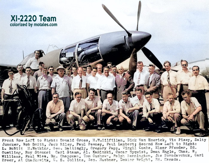
George Huebner, Chrysler’s Director of Research and the leader of the XI-2220 piston-engine project, knew as well as anyone that jets were the future, and he asked the Research Department to develop a gasoline turbine engine using company funds. Thus, in 1944—before the XI-2220 had its flight test—engineers Sam Williams and John Jones started work on a small gasoline turbine. Their experience in this field to date had mainly been designing and testing a supercharger for their giant piston engine.
While Jones and Williams investigated many possible designs, they had already decided to use a heat exchanger, which gathers waste heat from the exhaust; their thought was that they could use this heat to improve fuel economy, a major problem in gas turbines of that time. Today, though not at the time, a stationary heat exchanger is called a recuperator; a rotating heat exchanger is called a regenerator. Their setup had a stationery heat exchanger, but most histories call it a regenerator.
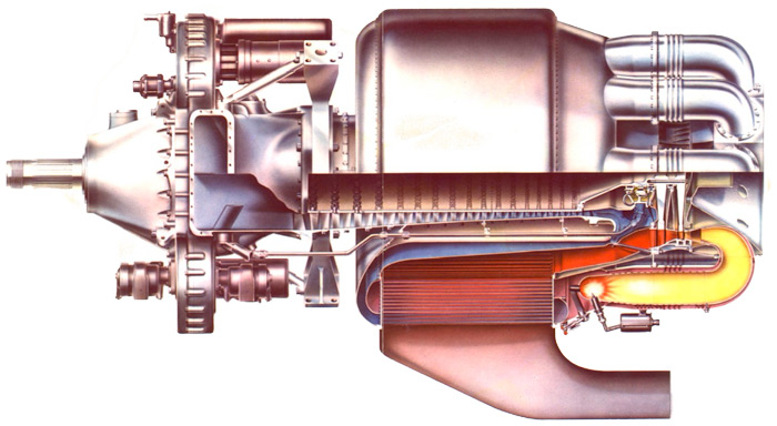
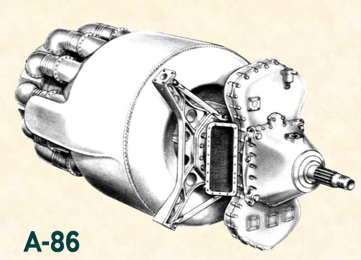
The elements of their final design (for this phase) included the heat exchanger, a burner and turbine, and an axial-flow compressor. This last item is a gas compressor made up of a bunch of airfoils mounted on a spinning shaft. The gas flows parallel to the rotation—axially. The advantages include constantly compressing the gas, high efficiency, high pressure capacity, and high flow rates for their size; but they are relatively complicated (due to needing several rows of airfoils) and expensive. Power was taken off via a reduction gear and shaft.
While they set up the basic design, Chrysler researchers worked on combustion and materials needs. As the piston aircraft engine project wound down, more engineers moved onto the turbine project.
The Navy, on hand for other reasons, found out about the research and looked at the test gear, then asked if Chrysler could adapt it to Navy aircraft. One unique part of the project was making the heat exchanger, or regenerator, part of the basic design rather than making it an add-on.
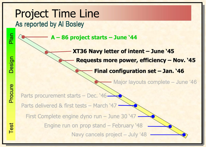
The Bureau of Aeronautics sent an official letter in May 1945 to confirm their needs; and Chrysler accepted, getting a letter of intent in July. Federal officials visited in October, meeting with Heubner as well as engineers Allen Staley, Dave Borden, and Tom Gleason. The officials noted that the original design studies assumed a 3.27:1 pressure ratio, a single-pass heat exchanger (regenerator), and a single-stage turbine with a 1500°F inlet temperature. The Navy wanted better fuel economy at partial loads, along with more power, which meant a higher compression ratio, better heat exchanger, and other changes, with a goal of 0.434 pounds of fuel per horsepower per hour in a plane at 30,000 feet and 60% cruise; they also demanded a rating of 1,000 hp at takeoff (at sea level), though this was not seen as being the most important rating.
The two groups rewrote the contract, Chrysler dubbed the project A-86 and the Navy called it the XT36-D2.
| Specification | Original | Revised |
|---|---|---|
| Pressure ratio | 3.27:1 | 6:1 |
| Turbine | 1-stage | 2-stage |
| Inlet temp | 1500°F | 1600°F |
The Navy was aware that while the contract was good for two years of research, the project itself would likely take much longer. Four amendments later extended the contract to mid-1949 and clarified that Chrysler was on its own, because the project was highly classified. It was not to exchange information with other turbine makers.
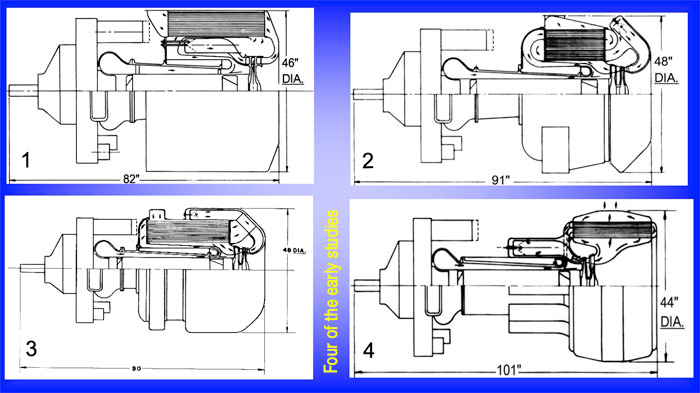
Engineers continued to look at overall layouts, taking the time to choose the ideal. The ideal for aerodynamics would be far too long; but having the components in parallel, while increasing the diameter somewhat, solved that problem. The compressor/turbine shaft bearings would be easier to support, as well; and putting the heat exchanger (regenerator) on the outside of the engine provided further support. The 1945 Study #13 was therefore chosen (in January 1946); it had a single-shaft axial-flow compressor driven by a two-stage axial turbine. As parts of the system were designed, the parts were specified and sent to the shop. As parts were made available, researchers tested individual components.
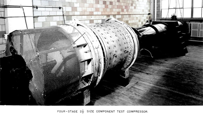
In March 1947, the group started using a 2.5:1 supersized four-stage compressor to test blade airfoils. It was built that large to match their dynamometer; but since it had the same ratio between inertial and viscous forces (and therefore turbulence), it was a good stand-in. Shortly after, they built a burner rig to test burner designs, and a full sized regenerator test setup. The latter was challenging; they had issues with leaks, and the first good sample finally ran in October.
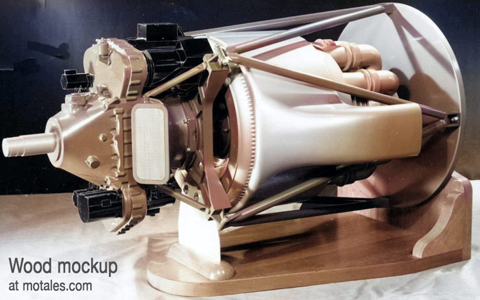
Chrysler set up a wooden half-sized mockup to make sure the parts worked together, and to finalize the cowling and exhaust.
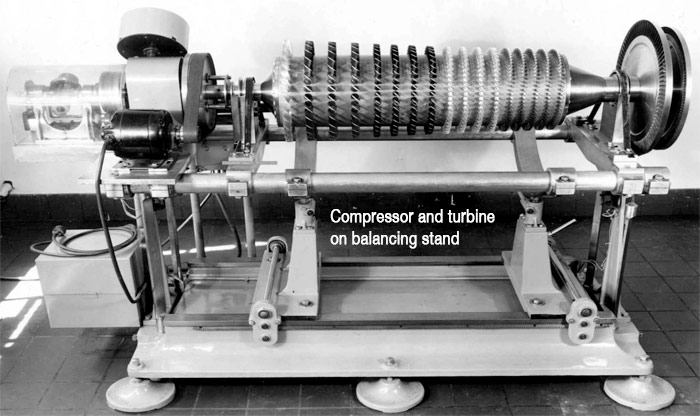
The setup they built, based on the thirteenth design study, was 45 inches in diameter and 91 inches long, with an aerodynamic housing for wing mounting. The compressor used an SAE 4340 steel rotor drum, a fifth of an inch thick, and nine and a half inches wide at the root of the blade. The rotor had fifteen blade rows, along with an inducer to bring air in and a final “exducer” to make sure the resulting airflow was a pure vortex. Bearing chambers were sealed with carbon rings and pressurized from the compressor. The shaft ran at 16,900 rpm with a 20,300 rpm overspeed setup at peak; the thrust bearing could carry a combined axial load of over 10,000 pounds, from the compressor and turbines. It was more efficient and lighter than an anti-friction bearing. The compressor could discharge air at up to 600°F and 95 psi.
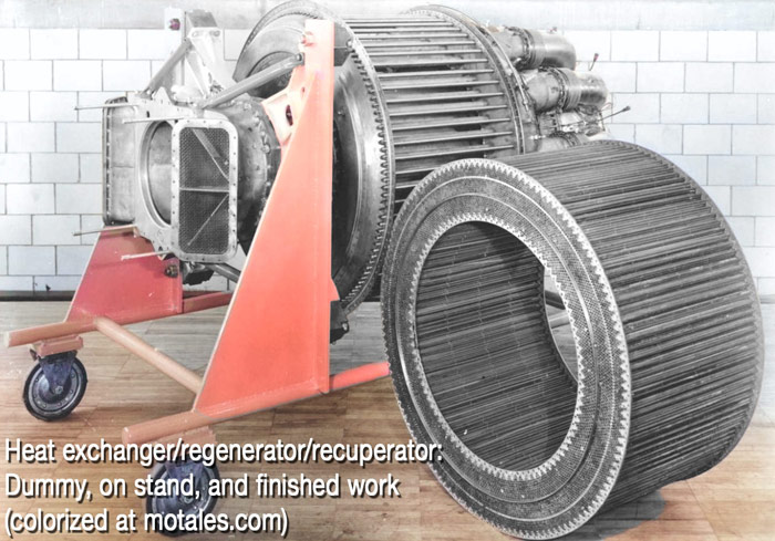
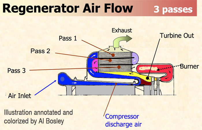
This system used a three-pass cross-flow heat exchanger (recuperator), rather than the original single-pass setup. Its shell was a cylinder, with an internal diameter of 26 inches and an outside diamter of over 36 inches; it was 20 inches long. Chrysler had asked Trane and General Motors for proposals on heat exchangers, but neither were as light or efficiant than Chrysler’s own setup. That used nearly seven thousand copper-brazed nickel-chromium Inconel tubes, with thick nickel end plates that, together, made the front and rear walls. The tubes were around 0.22 inches in diameter on the outside, with an incredibly thin wall thickness of just 0.005 inches. The inner and outer tube rows were somewhat thicker (0.02 inches) for more rigidity. Every tube had a spacer ring to prevent the gas passages from being blocked if the tube was bent. (Inconel is a “super-alloy” for extreme heat, pressure, or other stresses, made with a special process; it is still used for extreme temperatures, corrosive environments, and such.)
Air from the compressor went to the front chamber of the regenerator, and was then directed outward (radially, from the center) to pass through the 2,010 tubes in the outermost bank; it then turned back to go through the 2,352 tubes of the inner bank. The air in the tubes picked up heat from the exhaust gas on each pass. Finally, the exhaust went out through ducts, pointed aft to add thrust—217 pounds of it. The whole assembly weighed under 176 pounds, with 647 square feet of heat transfer area. At peak engine speed, the air passed to the burner chambers was at 1,200°F. Its effectiveness was 78% at idle, and 68% at takeoff. This design was tested for over 500 hours with no problems.
The full assembly was supported by the inner wall of the stator housing, which was made by 0.12”-or-thicker SAE 4130 steel. The blades were machined from magnesium alloy, except for the last five stages, which were machined from type 416 stainless steel. Each blade was held in place by a threaded shaft put into the compressor drum or stator housing, and fixed by both glue and a nut and washer; the glue helped lock the blade in place at the correct angle, set manually using a gauge.
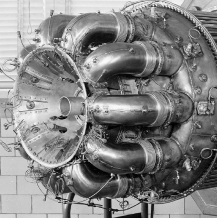
The burner took in air at 1,200°F from the heat exchanger. It had ten individual tube-shaped chambers around a central housing, with a sieve-style stainless steel (310) burner tube (“can burner” ) in each chamber. Air entered through the sieve holes. The nozzles and igniters were near the back of the engine to make them easier to service. Chrysler tested 18 nozzles from different vendors before choosing their own design, a return-flow nozzle. They tested but rejected cone type burners made of Inconel and stainless steel. The outgoing air, at up to 1,600°F and 86.5 psi (at sea level), went into the first stage turbine nozzle.
The two-stage turbine had forged discs and welded-on buckets with integral shrouds designed to reduce vibration. The two discs were made of different alloys, with different bucket materials; they were 16.3 and 18.1 inches, respectively, in diameter. Temperatures at both stages exceeded a thousand degrees (F). Nozzle blocks were made of Stellite, supported by the cast stainless steel turbine housing. Cooling was provided by an aft radiation shield, cooled with air bled from the compressor.
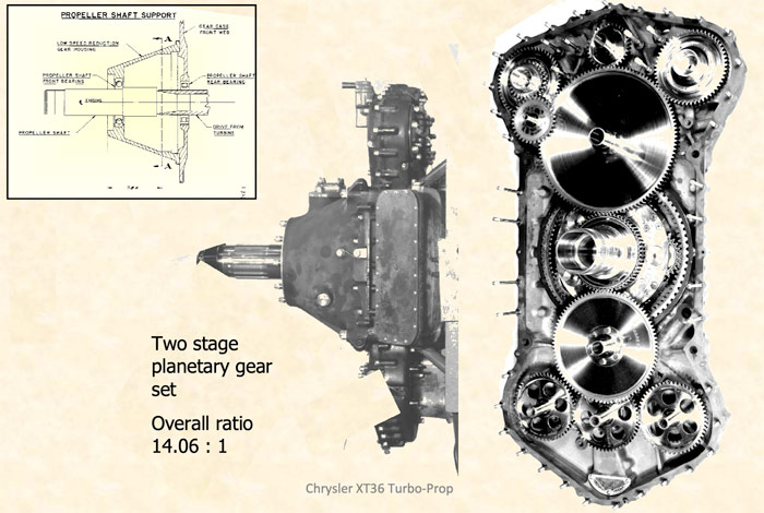
The cast magnesium gearbox was made of three pieces; it had a two-stage planetary gearset, with an overall gear ratio of around 14:1 to reduce the 16,900 rpm shaft speed to 1,200 rpm for the propeller. It supported the propeller shaft and accessories. The central housing included the dual inake ducts for the compressor. To equalize the loads, the high-speed and low-speed gear sets each used five planet gears instead of three. This required extremely tight machining, but the complex system was needed because 1,450 hp was coming from the shaft (which was supported on ball and roller bearings). The accessories were needed for spur gears to drive generators, a tachometer, fuel pumps, and such.
When it was all in done, the entire setup was pained with a special paint to resist abrasion and corrosion, even with exposure to salt water. It had been approved by the Navy in 1946; the major design work was done by the end of that year. The first test engine for the XT36-D2 was nearly ready, as a team started adapting the dynamometer, used earlier on the XI-2220 piston engine.
While the dyno had been unused, the Navy had discovered a Japanese experimental jet engine, inspired by a BMW jet whose plans had been shared by Germany in mid-1944. The Navy brought it to Chrysler to help give them experience in power testing; and they wanted to know its power ratings in any case. First they took apart the engines to create blueprints; then Bill Chapman ran one for nearly 12 hours, producing 1,050 pounds of thrust, using 1.55 pounds of fuel per hour per pound of thrust. That cleared the way for testing Chrysler’s own engine on June 30, 1947.
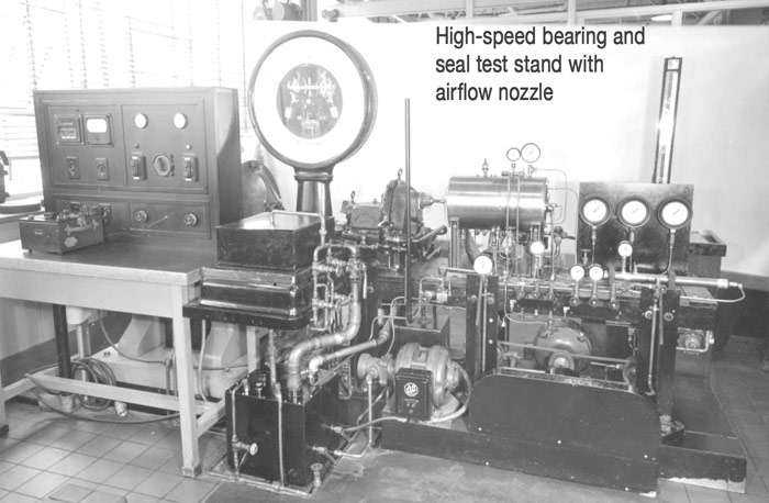
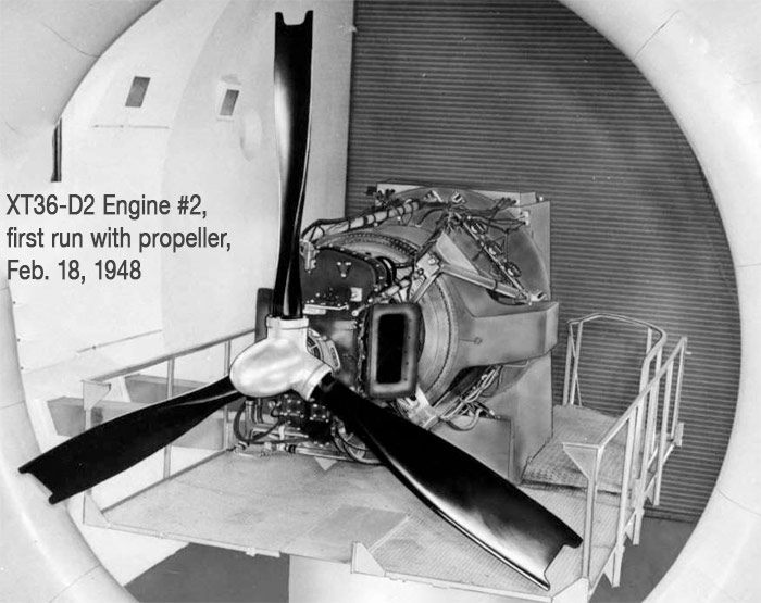
The early test engines, including the one tested, had been built without heat exchangers to measure the engine alone. Chapman found that the thurst bearing kept overheating, despite extensive testing earlier. Soon, he found the problem: the test rig rotated in the opposite direction of the engine itself. They made a new thrust bearing, with the correct tapers, and ran the engine for over four and a half hours until the compressor failed at 12,000 rpm. Some of the nuts which held the blades on had failed; they added positive locking rings to a new compressor and stator, then ran the engine for over 13 hours and took it off for inspection. The second engine was then run for around elevent hours, then put onto the propeller test stand with a three-bladed propeller. Two more compressor failures led the engineers to switch from magnesium to aluminum blades in the first twelve rows, and from magnesium vanes in the stator to steel. Then they ran the first four engines for a combined total of 610 hours; the second engine, which ran for 147 hours on the dyno and 144 hours on the propeller stand, was being prepared for a flight clearance test. It weighed 1,250 pounds.
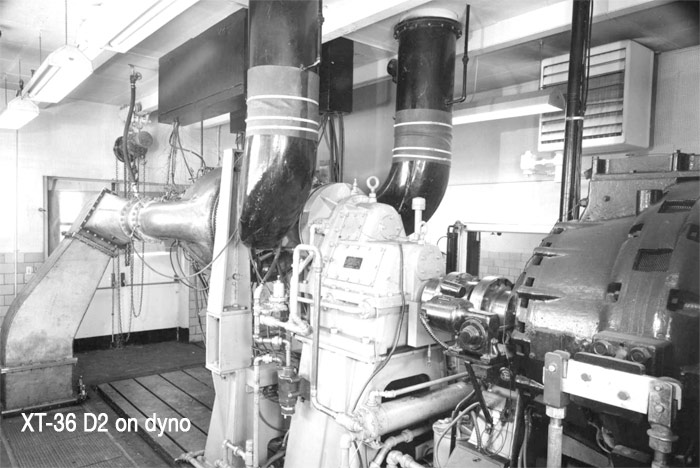
The power was not sufficient; it only generated 803 hp, and used too much fuel. Without the heat exchanger, it ran to 1,039 hp but fuel economy was even worse.
Even as the XT36-D2 was being assembled, the Navy and Chrysler had agreed on an upgraded second version, the A86B or XT36-D4 (Chrysler project and Navy designations, respectively). This version would have higher power, better economy, and longer life, achieved by increasing the temperatures from 1600°F to 2000° and then to 2400°. That program, led by Sam Williams, required a redesign of the back (aft) section.
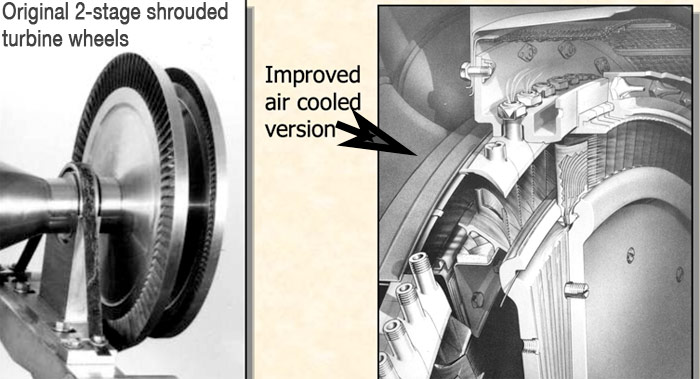
Williams created a new turbine and nozzle cooling setup, using air bled from the compressor to go through hollow nozzle vanes and turbine blades, which required a redesign of the turbine itself. The burner tube chambers were dropped, and all ten burner tubes were put into a single chamber. The turbine wheel bolts were replaced by a central shaft, held in place by one nut.
To handle higher power, the team had to rebuild the gearbox, this time using spur gears to handle up to 3,800 hp (2,800 hp was expected); it had new air inlet ducts as well, to increase airflow to the compressor. Parts were on order by March 1948, and Chrysler planned test the system at the end of 1949. However, the contract ended in mid-1949, and the Navy chose not to renew the contract. The company believed they could resolve these problems with the new version of the engine, and why the Navy dropped the contract is an open question. Robert F. Pauley speculated that budget cuts may have been one reason; in addition, the Navy needed more thrust for faster speeds, and had less concern about fuel economy.
The Stalker Development Company had been contracted to develop a boundary layer control compressor for the engine. The company had been created by aeronautics engineer and University of Michigan professor Edward Stalker, who had created the boundary layer control theory. His compressor proposal, with just eight stages, would replace Chrysler’s 17-stage unit; it was shorter, weighed less, and was presumably cheaper. However, Stalker was never able to create the needed parts and balance the rotor. His incomplete unit was sent to the Navy when the contract ended, but never ran.
The program was switched back to its original goal, passenger cars. In 1954, Chrysler showed off its first turbine cars to the media. For passenger cars, the turbine was never going to work well; its problems included extreme heat, cost, response time, and fuel economy, though it could in theory work on practically any combustible fuel. Mr. Pauley was not aware of any surviving engines or components.
George Huebner, born in 1910, started working at Chrysler in 1931 with a degree from the University of Michigan; before joining the research division, he was assistant chief engineer of Plymouth. William Chapman graduated from Iowa State and went to Chryselr in 1941; after the aviation programs he worked on the gas turbine, then left to Ford where he worked on Ford’s new gas turbine engines. In 1974 he joined Williams Research, where he worked through 1993. Dr. Sam Williams graduated from Purdue and joined Chrysler in 1942 as a research engineer; in 1949 he was promoted to manager of the design department, where he was in charge of the A-249 gasoline turbine. John Jones, Sam Williams, and one other employee left in 1954 to form Williams Research, which made turbine engines for drones and missiles. John Jones had graduated from Case Western Reserve; he died as vice president of engineering at Williams in 2000.
Robert Pauley joined the Research Department in 1953, leaving for Williams International (née Williams Research) in 1981. Al Bosley entered the Chrysler Institute in 1953, worked in Chassis Engineering, and rose to become Director of Corporate Information Systems Planning. He returned to Engineering for prior to his retirement in 1991.For more details and diagrams, see Torque Meter, 6(1), Winter 2007.
Copyright © 2021-2025 Zatz LLC • Chrysler / Mopar car stories and history.
YouTube • Editorial Guidelines • Videos
Tailfins Archive • MoTales on BlueSky