Chrysler Corporation’s first completely new four-cylinder (not counting inherited Maxwells) was the 2.2 liter created for “K-cars.” It made a splash when launched, but a decade later, head of engineering Francois Castaing wanted to start over for “the New Chrysler.” The 2.2 was “old tech,” though in turbocharged form it was surprisingly capable, generating up to 224 hp.
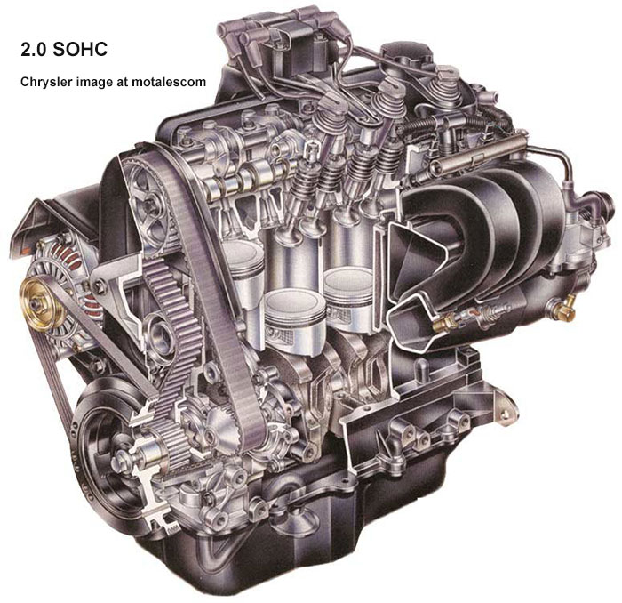
For global tax reasons, the new engine had to displace less than 2 liters—say, 1.996 liters—with enough power to beat every other engine in its class, and better fuel economy and power than the 2.2. The outgoing 2.2 was rated at 93 hp and 121 lb-ft, a rather torque-biased setup; journalists generally agreed that the top mass-market four was the Honda Civic Si’s 1.8, rated at 125 hp and 100 lb-ft. The new 2.0 would easily beat both, in both horsepower and torque.
The new Chrysler engine, coded A597, is still often informally called the “the Neon 2.0” because it launched in the 1995 Neon. A long-stroke version, the 2.4, was unveiled later in the that model-year for midsized cars and then minivans; the two shared a block, differing in the heads and other parts. Other versions included a 1.8 liter for markets where economy trumped power, and 1.4 and 1.6 versions for early New Minis and export Neons, respectively. These were later used in South American Fiats as the eTorQ.
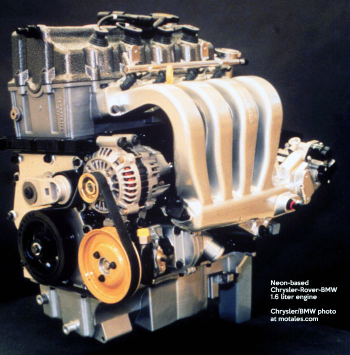
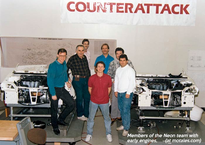
The 2.0 was engineered by Chrysler, though some still believe that it was a Mitsubishi engine. It was engineered in software, using CATIA; the data was converted directly to patterns for die makers, cutting tooling time and allowing cheaper, faster production of prototype engines. This new car was a matter of pride for Chrysler employees: it would prove they could go up against the best in the world on their own turf—that they could better the pride of Japan. Beating the much-praised Honda Civic would be a major achievement; the automotive press and popular opinion had already judged GM, Ford, and Chrysler as being incapable of that feat. It was time, the team thought, to counterattack.
The Neon 2.0 started with 132 horsepower and 129 lb-ft of torque at a time when most of its rivals failed to beat 100 horsepower; Honda made nearly as much horsepower, but only hit 100 lb-ft of torque. The even balance of horsepower and torque was new for a company that had always favored torque; Floyd E. Allen, executive engineer for small car platforms, said the more even balance was meant to “achieve that fun-to-drive feeling.”
The engine had a flat torque curve for the time, with 90% of peak torque available at 2,000 rpm; it peaked at 5,000 rpm. Weight came in at just 242 pounds. Overall, especially coming from Chrysler, it was a wonder; when Neons came out, Toyota was one of the first buyers, to strip it down and learn its secrets.
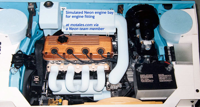
The twin cam 2.0 was rated at 150 hp in the Neon, 140 hp in midsized cars and Mitsubishi coupes. The power helped the 1995 Neon (SOHC and DOHC alike) to run from 0 to 60 mph in under 8 seconds, according to every magazine except Consumer Reports. That made it quicker than just about all its competitors; at the same time, the interior was larger than most, and handling was at the top of the class.
Neons were top contenders in true stock car racing, dominating their classes in SCCA racing for years. BMW seriously considered using the engines instead of their 1.8s in the 3-series.
The long-stroke version, displacing 2.4 liters, was a twin cam design; one version was used in the Dodge Stratus (launched in May 1995 and followed by the Plymouth Breeze), and one for the 1996 minivans. The head and intake were taken from the 2.0 DOHC, but the block was new; it produced nearly the same power and torque as the 3-liter Mitsubishi V6. The 2.4 will be covered more deeply in a future story.
To use existing equipment and tooling, the 2.0 and 2.4 had the same bore and 96 mm (3.8”) bore centers as the 2.2 and 2.5 liter engines; the block was designed for that bore and no more. Coolant flowed around all the cylinders.
The bores and bore centers were the same as the 2.2, but the 2.0 had few parts from previous engines; powertrain executive Floyd Allen said, “The only link it has to our previous 4-cylinder engine family (2.2 and 2.5 liters) is that it shares the same bore centers.” (There were some similarities to the 2.2 in the lower end of the block, but nothing interchanged.) The stroke was shortened from the 2.2’s 92 mm to 83 mm, partly to keep the engine small enough for the Neon’s low hood, partly to keep the displacement just below two liters.
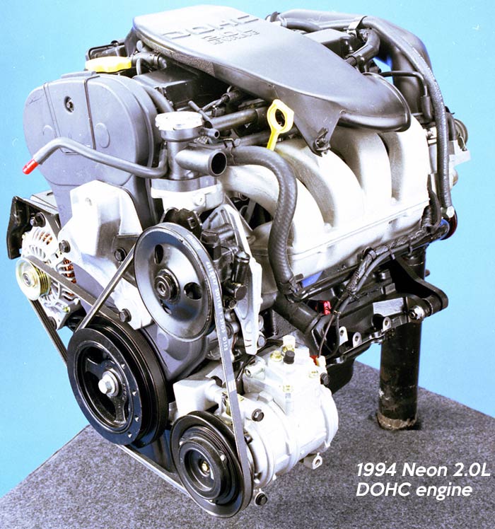
The cast iron block had a shallow skirt, with a bolted-on (with 20 bolts) cast iron bedplate underneath; the bedplate, a perimeter wall, and transverse webs added rigidity. Cast iron was likely chosen over aluminum for cost reasons. The deck was 8.35 inches (212 mm) high, ending at the centerline of the crankshaft, using an open top deck and including a cast-in water pump housing in front.
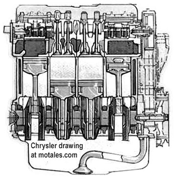
The three displacements (1.8, 2.0, 2.4) all used the same cast-iron block castings, though the 1.8 had a smaller rough bore. The 1.8 and 2.0 shared rods and cranks; the blocks were made on the same line, and from time to time employees tried to finish a rough-bored 1.8 block to the bigger 2.0 liter bore, causing a good deal of tooling damage.Connecting rods and rod caps were forged from powdered (sintered) metal and machined in a single piece, then cracked along a laser-cut line to create a perfectly matching surface. That lowered weight and increased dimensional control. This was the first time this process was used in the auto industry, but not the last; and the company’s V6 engines switched to the new rods later.
Cap bolts were threaded into the rod shank. Cast aluminum-alloy pistons (with 12% silicon to reduce wear) had shallow crowns and an elliptical shape to control expansion. The tops of the pistons had notches to make room for more valve lift.
To reduce vibration, the engineers cut the pistons and rod mass. Floyd Allen said, “On a relative bore size basis, we have one of the lightest pistons in the industry. It’s a relatively large bore/short stroke engine, which again is favorable from a secondary order vibration perspective.” On the 2.4, the engineers essentially re-used the old 2.5 engines’ balance shaft design.
The 2.0 came with single or dual overhead cams; the dual cam version had a higher peak horsepower number (150 vs 132), but wasn’t much different in day to day driving. The heads for both were similar to Mitsubishi designs—the SOHC borrowing from the 1.5 liter Colt engines, and the 2.0 from the bigger Mitsubishi twin cam engines. Both had pent-roof designs. The two DOHC designs, 2.0 and 2.4 liters, shared the same heads; but the 2.4 had a different block to deal with its 101mm stroke. This block had a 237.8mm deck, the same as the old 2.2/2.5 block, as a result (the journals were beefed up to match those of the 2.2/2.5 as well).
The cross-flow cast aluminum cylinder head had four valves per cylinder. Spark plug tubes were pressed into the head and held with anaerobic sealer, sealing against the underside of the cylinder-head cover. Intake ports were designed to increase turbulence (“air tumbling”), speeding combustion; both ports led to a single branch.
The original head gaskets were meant to be a triple-layer “sandwich” (MLS) design; these were turned down by a high level executive, who insisted on something cheaper. For that reason, just about all engines made 1995-97, and some early 1998 engines, had head gasket failures within 60,000 miles. Afterwards, something similar to the original head gasket design was swapped in, and failures were a thing of the past. The other weak spots of the early engines included the mounts, which were fairly easy to replace, and early coils.
Cast aluminum valve covers had black enamel finishes, with the engine size and, with twin cams, the legend “DOHC” (SOHC engines had a different legend). The valve covers had an isolated mounting with a silicone gasket, and an integral coil mount.
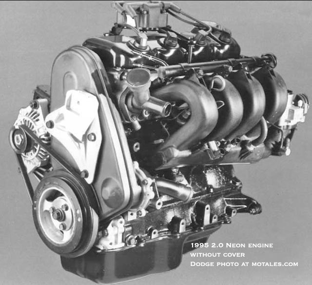
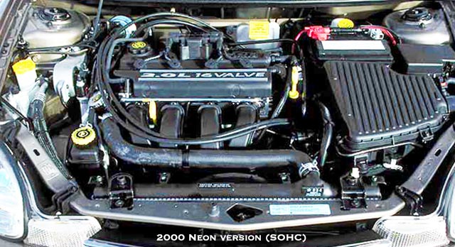
The Neon SOHC had used a revolutionary 30%-glass-filled nylon intake which provided a much smoother air path and weighed five pounds less than an aluminum intake would. Air came through a remotely mounted filter in an easily-removed housing (to provided access to the oxygen sensor); then went through a large duct into a tapered plenum and elbow section, finally moving through curved 16.5 inch (420 mm) primary runners, whose length optimized low-rev torque. The manifold was attached with compression limiters to avoid damage.
The tuners created two different throttle bodies, one for the manual transmission and one for the automatics, with contoured bores in the off-idle area that limited airflow at low throttle. The automatic was designed for a hefty tip-in, and used a 52mm maximum bore; the manual had a gentler tip-in for smoother shifting, and a 48mm bore (on the DOHC, even manual transmissions had a 52 maximum bore, but the tip-in was still gentler due to the contours). Some enthusiasts used automatic throttle bodies on the manual, which made gentle shifts into first more difficult.
The DOHC engines had two intakes. The “cloud cars” (140 hp) 2.4 had a single-piece cast aluminum intake with a 15.7” runner length. The minivans had a two-piece cast aluminum intake with 18.5 inch (470mm) runners. Eventually these were all replaced by the plastic intakes, which were lighter and flowed better.
Regardless of version, the engines had recirculated exhaust gas (EGR) entering the manifold at the base of the throttle body. The thin-wall cast nodular iron exhaust manifolds had a four-into-one runner design; the outlet flange mated with a sealed flex coupling on the exhaust pipe, dubbed the “exhaust donut.” This was problematic on early Neons, causing noise.
The engine had 16 valves, two intake and two exhaust for each cylinder (the 2.2 had 8 valves, other than the Turbo III, whose heads were designed by Lotus). The cam in the SOHC was centrally mounted. The cams had no bearing inserts, operating directly in the head.
| SOHC | DOHC 2.0 | 2.4 | |
|---|---|---|---|
| Intake valve | 1.3” (33 mm) | 1.36” (34.5 mm) | 1.4” (35.5 mm) |
| Exhaust valves | 1.1” (28 mm) | 1.16” (29.5 mm) | 1.2” (30.5 mm) |
| Included angle | 42° | 48° | 48° |
The SOHC intake valves had a 42° included angle (exhaust valves rearward, intake valves forward); intake valves were splayed 3.6° to clear the spark plug tubes. Valve seat inserts were made of sintered (powdered) metal, and valve guides were pressed into the head.
Three aluminum rocker arms opened the valves—two for the twin intake valves, and one for the twin exhaust valves; the rocker arms had tiny hydraulic adjusters in their valve tip ends (one adjuster for each valve). On the other side, roller followers stayed in contact with the camshafts. Redline was at 7200 rpm.
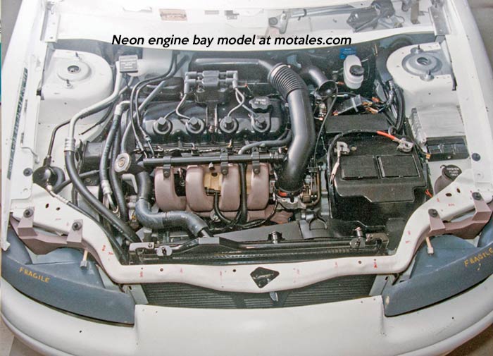
The DOHC had larger valves, with quarter-inch (6 mm) chrome-plated stems. Valve lift was 0.31 in. (7.8 mm) on the intake and 0.28 in. (7.0 mm) on the exhaust. The included angle was 48° rather than 42°, with the angles reversed—exhaust valves forward, intakes rearward. Each valve was operated by an end-pivot rocker arm; the 0.79 in. (20 mm) roller cam followers ran on roller bearings. Redline was the same as in the SOHC—7200 rpm.
The 2.4 cam had a 236° intake duration and a 240° exhaust duration; the intake cam centerline was 113° ATDC, and the exhaust was 110° BTDC, with 15° of overlap. Intake valve lift was 0.33 inches (8.25 mm) and exhaust valve lift was 0.26 inches (6.5 mm).
The hardened nodular iron camshaft had three lobes per cylinder, two for the intake valves and one for the exhaust valve; it moved aluminum center-pivot rocker arms with roller bearing cam followers and hydraulic lash adjusters. The cam had a 75% balance ratio. Forked exhaust rockers could operate two valves at once. Single beehive valve springs were used for each of the valves—a move made possible by their light weight.
The cam was driven by a cog belt, kept at the right tension by a spring-loaded device with hydraulic damping pushing an idler pulley against the back of the belt; this was designed to be replaced, with the belt, at around 100,000 miles (press materials said it was good for the life of the vehicle). Low-inertia sprockets were made of powdered metal; DOHC engines had one for each cam. The belt, specially designed for higher strength and durability and spaced away from the engine to reduce temperatures, was enclosed by a two-piece plastic cover. The camshaft did not need bearing inserts. The dual cam setup used six bearings with removable caps machined in the head base material; they also used powdered metal valve seat inserts and valve guides pressed into the head.
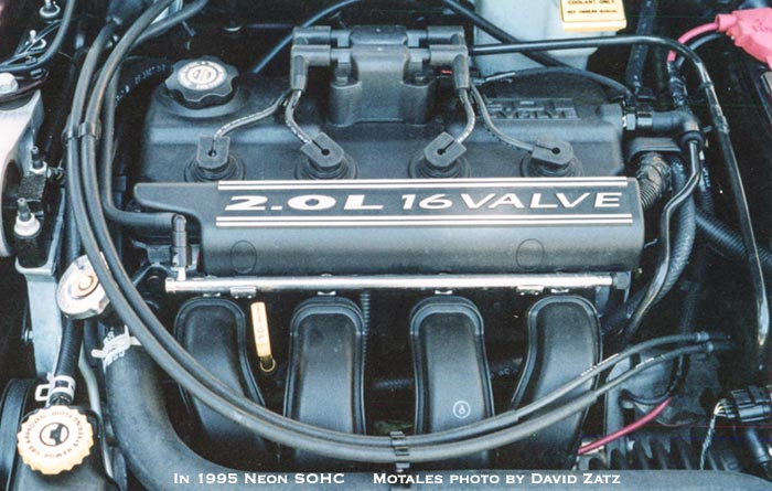
The modular iron crankshaft had counterweights on both sides of each crank pin to balance the bearing rods, allowing for smaller bearing diameters, which cut friction. The crank weighed 33 pounds (15 kg) on both 2.0 engines. The main bearings were 20% smaller in diameter (at 52mm) than they would have been in past Chrysler engines; the rod bearing diameters (at 48mm) were 8% smaller. Main and rod bearings had bi-metal inserts and lower tolerances than in past Chrysler engines. A conventional inertia-ring vibration damper was mounted on the crankshaft; it included pulley grooves which drove the alternator and accessory belts.
The powdered-metal gerotor oil pump, contained in an aluminum housing, was driven by the crankshaft; the block itself was inclined slightly to the rear of the car for better oil drainage. The engine took four quarts of 5W-30 oil, plus filter. The filter was mounted to an extension for easier access. The water pump, driven by the timing belt, used a housing built into the block.
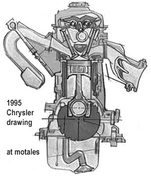
The oil pan in later vehicles was stamped from acoustically damped material (two layers of steel around one layer of mastic) to cut noise, and was designed to prevent oil from being aerated. The crankcase ventilation system had an oil separator in the valve cover to reduce high speed pullover.
The water pump was cast into the block, and driven by the timing belt. A single molded plastic unit combined the thermostat housing, filler neck, radiator hose nipple, and overflow nipple. The thermostat included an air vent and check ball to let air escape when the system was cool, but preventing swings in coolant temperature and making refills easier with no need to “burp the system.” That also prevented head gasket failures caused by bubbles in the antifreeze. The filler neck was attached to the thermostat housing because it was the highest point in the system—above the top of the radiator. Thus, the “radiator cap” was fitted to the thermostat housing’s filler neck.
The 2.0 engines were far more tightly sealed than past Chrysler engines, by design. The rear main seal had a Teflon lip and was pressed directly into the black-and-bedplate assembly, instead of into a housing. The oil pump cover also housed the crankshaft front main seal. The oil pan and head gaskets were molded silicone with steel backbones and compression limiters; the oil pan drain plug had a molded seal. The block bedplate and top surface of the cylinder head were machined flat for better sealing; spark plug tubes had individual molded seals; and a molded silicone-rubber gasket created a good seal between the thermostat housing and the head. Sealing was far better than in the old 2.2 and 2.5 liter engines—oil seepage was relatively rare.
The head gasket was the only major sealing issue. Engineers had reportedly specified a multi-layer setup from the start, but it was rejected to reduce costs. In reality, the cost of replacing head gaskets on every 1995, 1996, and 1997 Neon far exceeded the extra cost of putting better head gaskets on to begin with; and a new multiple layer head gasket was installed starting in the 1997 or 1998 model year.
The sequential multi-port injection system relied on cone-spray injectors, one per cylinder; slots on the top of the intake ports oriented the injector to spray directly into the open valves (unlike non-sequential designs, there was no spraying onto closed valves).
The computer had some clever fuel control systems; returnless injection, where the regulator was kept in the fuel tank, meant that the computer had to adjust injector controls to deal with changes in fuel pressure at the engine. In addition, the software tried to reduce driveline shock using fuel flow control.
The computer used a stepper motor and bypass valve in the throttle body to set idle speed; it would increase the idle under at least three conditions—
The crankshaft sensor sensed two patterns of four slots in the counterweight to figure out where the crankshaft was; the camshaft sensor on the rear of the head, sensed a ring magnet in the end of the camshaft. The computer used these sensors to decide which cylinder should get fuel and spark, and how to set the spark advance. The cam position could be found in less than one turn of the crankshaft, making fast starts possible.
The ignition used a four-lead coil pack; the spark plugs went into the center of the combustion chamber through cast wells. DOHC versions had a knock sensor.
The computer used engine speed and intake manifold pressure (MAP sensor readings) as the primary ways to set fuel injection rate and timing; it measured engine speed with the crank and cam sensors.
The crankshaft drove the alternator via one belt and the power steering and air conditioning from a separate belt. The belts were attached to one damper and adjusted with a pivoting bracket. While technically not part of the engine itself, the cruise control used a vacuum servo to pull a cable and open the throttle, which a reserve system to keep vacuum on steep grades.
The engine was retuned for the 2000 Neon, slightly increasing torque (132 hp at 5600 rpm and 130 ft-lb at 4600 rpm). A related 1.6 liter engine, developed from the Neon 2.0 with Austin, produced 115hp (85kW) and 157 Nm torque for displacement-tax countries.
The new 2000 Neon was bigger and heavier than the original, and other automakers had bolstered their own output, so the 2.0 had a harder time producing competitive speeds; Chrysler compensated with aggressive gearing. In the UK, the new Neon’s mileage was rated at around 29.4 mpg (manual) and 26 mpg (automatic), after converting from Imperial gallons, combined city/highway ratings; 0-62 mph (0-100 km/h) times were 10.8 seconds for the manual, 12 seconds for the automatic.” This poor performance is odd since the US version was rated at around 8.1 seconds 0-60 with 28 city, 34 highway.
For 2001, higher-performance Neons had a single-cam Magnum engine which produced a hefty 150 hp and 135 lb-ft of torque. City economy was identical to the regular 2.0 while the highway mileage was slightly higher. How, one may wonder, did Chrysler extract so much more power without hurting gas mileage? The answers were in an electronically controlled dual-plenum intake, which could take advantage of supercharging effects in two different engine ranges; dual exhausts and mufflers, with 2.25 inch pipes and stainless steel headers, to reduce resistance; and a new camshaft tuned to take advantage of the lower back pressure and new intake. Only select Neons had this pricier engine, which replaced the DOHC in the Neon (other cars with the 2.0 DOHC kept it).
Related 2000 Neon specifications
| Construction | Cast iron block and bedplate Aluminum alloy head Structural aluminum oil pan |
| Power | 132 bhp (98 kW) @ 5600 rpm (66.2 bhp/liter) |
| Torque | 130 lb.-ft. (177 N-m) @ 4600 rpm |
| Redline | 6750 rpm manual, 6720 automatic |
| Fuel | Unleaded regular gasoline, 12.5 gallons |
Other updates were:
From 1994 to 1999, the SOHC 2.0 engine produced 132 bhp (98 kW) at 6000 rpm and 129 lb-ft (174 N-m) at 5000 rpm. The 1995 SOHC and DOHC Neons were both rated at 29 mpg city, 38 highway with the five-speed manual. The 2000-2004 Neons varied quite a bit as gearing was altered.
The DOHC version produced 150 horsepower in the Neon, with the same torque; and 140 horsepower in the Mitsubishi Eclipse and Eagle Talon, where, to fit under the hood, the manifolds were reversed. Generally, the DOHC engine’s advantages didn’t show up until the engine was revved quite a bit.
| 1995 | SOHC | 2.0 DOHC | 2.4 |
|---|---|---|---|
| Bore | 3.44 (87.5 mm) | ||
| Stroke | 3.27 (83 mm) | ← | 3.98 (101 mm) |
| cc | 1996 | ← | 2429 |
| cubic inches | 121.8 | ← | 148.2 |
| Compression | 9.8:1 |
9.6:1 | 9.4:1 |
| Fuel | Reg. | Reg. | Reg. |
| Horsepower | 132 |
150 | 150 |
| Lb-ft | 129 |
131 | 167 |
| Rod length | 5.47” (139mm) | ← | 5.94” (151mm) |
| Block height | 8.35” (212mm) | ← | 9.36” |
| Block length | 16.43” | ||
| Valve included angle | 42° | 48° | 48° |
| Cams | One | Two | Two |
The 1.8 and 2.0 engines were primarily made at the Trenton engine plant. The 1.4 and 1.6 versions were made in Brazil. The 2.4 was made in Mexico. Blocks for the single-cam were made in Trenton and blocks for all dual-cams, including the 2.4, were made in Mexico.
Copyright © 2021-2025 Zatz LLC • Chrysler / Mopar car stories and history.
YouTube • Editorial Guidelines • Videos